
Thermoset Hydraulic Transfer Molding Machine
Han Chang Machinery manufactures this pot-type Bakelite transfer molding machine for transfer-grade phenolic (PF/Bakelite) and urea-formaldehyde (UF) compounds. Typical applications include switch bodies, plug and socket insulators, and metal-insert parts. An operator manually charges the upper pot; with the mold closed, an upper hydraulic plunger forces compound through runners and gates into the cavities for heat curing.
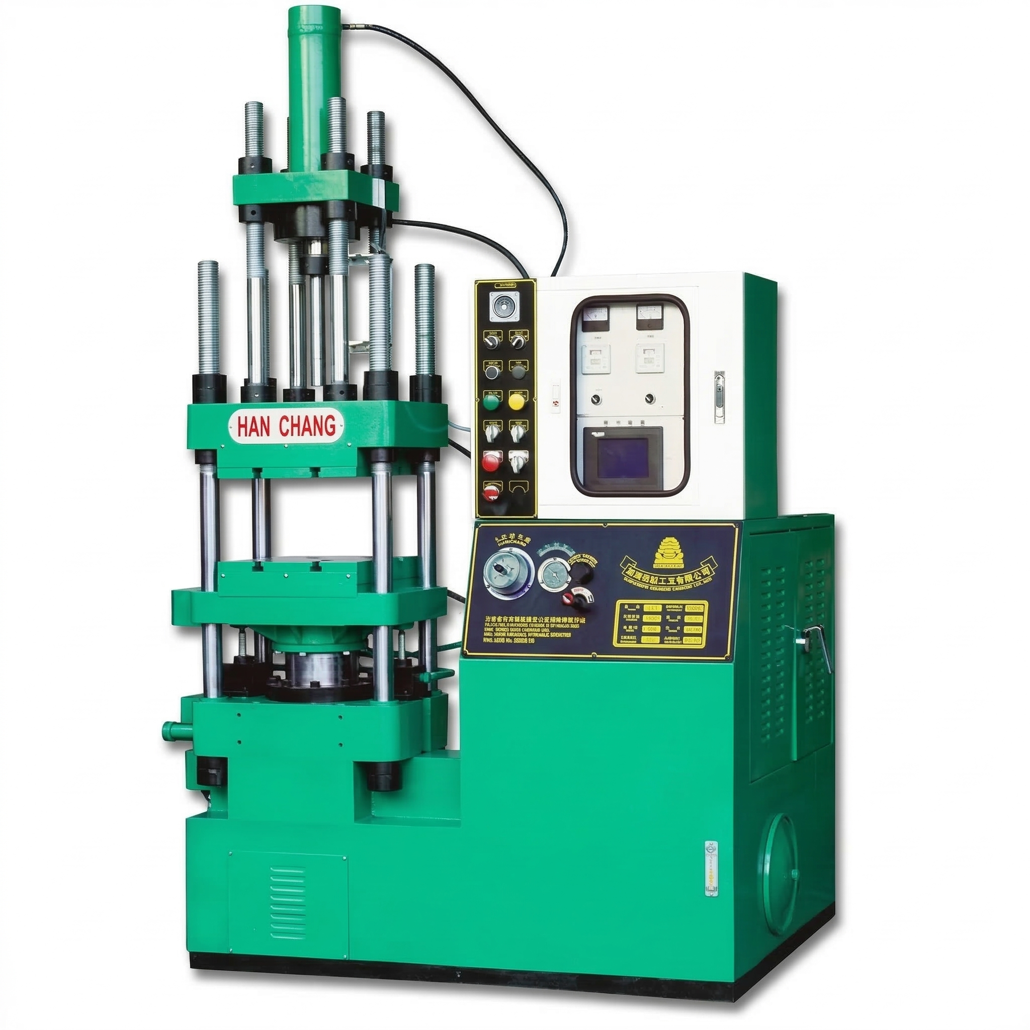
Machine advantages
One centrally loaded pot supplies the cavities through a runner network, making this process a practical choice for multicavity insulation parts. Metal terminals can be located before filling, while insert-free supports use the same transfer principle. The standard range lets buyers match clamping force and mold space to the tooling, then select the transfer arrangement for the complete charge and operator access.
Locate the metal before molding the body
Terminals, bushings and nuts are positioned in the tooling before the compound enters. This allows a metal connection or fastening point to be combined with the thermoset insulating body during molding. Tooling location features and the runner layout define how material reaches the insert and which areas are covered.
Charge one pot to feed a multicavity tool
The operator loads the transfer pot rather than placing compound directly into each cavity. Runners and gates distribute that charge to the molding cavities. For repeated small insulation parts, this concentrates manual charging at one location and gives the mold designer a defined feed path for each cavity.
Use the process with or without inserts
Metal inserts are a part-design choice, not a requirement for transfer molding. A terminal-bearing body and an insert-free insulation support can both be planned around pot feeding, closed-mold filling and heat curing. Each tool is matched to the press by its mold-space and charge requirements.
Select for working clearance, not tonnage alone
The standard specifications let buyers compare clamping force with platen dimensions, stroke and maximum opening. Reading these together helps accommodate the tool, its mounting points and the space needed to place inserts and remove parts—not just the closed mold envelope.
Pot-type transfer molding process
Measure and load the charge
Prepare the compound needed for all cavities, runners and pot-cull residue. The operator manually loads the measured charge into the upper transfer pot.
Position any metal inserts
For insert-molded parts, locate terminals, bushings or nuts in the tooling before closure. Omit this step for insert-free parts. The order of pot charging and insert placement can follow the working arrangement.
Close and clamp the mold
The mold closes and is held clamped before the plunger transfers material into the cavities.
Transfer through the runners and gates
The upper hydraulic cylinder drives the plunger downward. Compound moves from the pot through the sprue, runners and gates, filling the closed cavities and the specified areas around any inserts.
Cure under mold heat and pressure
The thermoset compound cures in the heated mold during the pressure-holding stage. Molding conditions are matched to the compound grade, part thickness and tool design.
Open, remove parts and clear residue
After curing, the mold opens and the operator removes the parts and clears runner and pot-cull residue before preparing the next charge and any inserts.
Materials and product applications
Switch bodies and rotary-switch insulation parts
A switch body supports contacts and operating components while separating conductive areas. In a transfer-grade phenolic or UF design, the runner system directs compound around ribs, holes and terminal locations after the mold has closed. Pot-type transfer molding is a useful process choice when the insulating structure and the position of embedded terminals need to be established in the same tool.
Plug and socket insulators
These bodies support pins or contact components and maintain their assembly positions. In insert-molded designs, the metal is located before closure and compound fills the intended insulating areas; tooling defines the exposed contacts and assembly faces. A Bakelite transfer molding machine is relevant here because it combines contact positioning and insulating-body molding within one tool.
Terminal blocks and fuse holders
Terminal blocks separate adjacent wiring connections, while fuse holders support the protective element and its contacts. Barriers, fixing holes and terminal locations make the feed path an important part of the tool design. For repeated parts in a multicavity mold, one pot supplies the cavities through a runner network, concentrating the loading task rather than requiring a separate compound charge in every cavity.
Thermoset parts with bushings, nuts or terminals
A metal bushing or nut supplies a connection or fastening point; the surrounding molded body supplies support and insulation. Positioning the insert before closed-mold filling allows both elements to be combined during molding. This is a practical purchasing reason for transfer insert molding when the product calls for embedded metal rather than a separately fitted component. Tooling location and shutoff features define the covered areas and keep required threads or contact faces exposed.
Appliance insulation supports and spacers
Internal supports, mounting blocks and spacers hold appliance components and separate conductive or hot areas. Insert-free designs also suit the pot-fed process: the runners bring compound to the molding areas, and multicavity tools can be supplied from a centralized charge. Select a transfer-grade compound and part structure for the required electrical, thermal and mechanical duty, then verify the molded component against its finished-product requirements.
Specifications and machine selection
Standard models are HCF-50, HCF-70, HCF-80, HCF-100, HCF-150 and HCF-200. Use the table to compare clamping force, platen dimensions, stroke, daylight and installation data. Match the mold footprint and closed height, then allow room for insert placement and part removal.
Spec / Type HCF-50
| Clamping force (Ton) | 50 |
|---|---|
| Plate size (m/m) | 380×380 |
| Cylinder diameter (m/m) | 190 |
| Stroke (m/m) | 300 |
| Daylight (m/m) | 580 |
| Pump pressure (kg/cm2) | 210 |
| Motor (HP) | 3 |
| Heater capacity (Kw) | 5 |
| Oil reservoir capacity (gallon) | 50 |
| Machine size LxWxH (m/m) | 1600x1050x2350 |
| Net weight approx (kg) | 2000 |
Spec / Type HCF-70
| Clamping force (Ton) | 70 |
|---|---|
| Plate size (m/m) | 420×455 |
| Cylinder diameter (m/m) | 212 |
| Stroke (m/m) | 380 |
| Daylight (m/m) | 620 |
| Pump pressure (kg/cm2) | 210 |
| Motor (HP) | 3 |
| Heater capacity (Kw) | 5.5 |
| Oil reservoir capacity (gallon) | 55 |
| Machine size LxWxH (m/m) | 1600x1150x2400 |
| Net weight approx (kg) | 2650 |
Spec / Type HCF-80
| Clamping force (Ton) | 80 |
|---|---|
| Plate size (m/m) | 485×465 |
| Cylinder diameter (m/m) | 236 |
| Stroke (m/m) | 410 |
| Daylight (m/m) | 630 |
| Pump pressure (kg/cm2) | 210 |
| Motor (HP) | 5 |
| Heater capacity (Kw) | 6 |
| Oil reservoir capacity (gallon) | 70 |
| Machine size LxWxH (m/m) | 1720x1200x2605 |
| Net weight approx (kg) | 3150 |
Spec / Type HCF-100
| Clamping force (Ton) | 100 |
|---|---|
| Plate size (m/m) | 600×550 |
| Cylinder diameter (m/m) | 265 |
| Stroke (m/m) | 460 |
| Daylight (m/m) | 750 |
| Pump pressure (kg/cm2) | 210 |
| Motor (HP) | 5 |
| Heater capacity (Kw) | 10.6 |
| Oil reservoir capacity (gallon) | 100 |
| Machine size LxWxH (m/m) | 1840x1250x2825 |
| Net weight approx (kg) | 4100 |
Spec / Type HCF-150
| Clamping force (Ton) | 150 |
|---|---|
| Plate size (m/m) | 660×620 |
| Cylinder diameter (m/m) | 300/315 |
| Stroke (m/m) | 480 |
| Daylight (m/m) | 780 |
| Pump pressure (kg/cm2) | 210 |
| Motor (HP) | 7.5 |
| Heater capacity (Kw) | 10.6 |
| Oil reservoir capacity (gallon) | 100 |
| Machine size LxWxH (m/m) | 2025x1350x2825 |
| Net weight approx (kg) | 4910 |
Spec / Type HCF-200
| Clamping force (Ton) | 200 |
|---|---|
| Plate size (m/m) | 660×620
720×720 |
| Cylinder diameter (m/m) | 368 |
| Stroke (m/m) | 500 |
| Daylight (m/m) | 820 |
| Pump pressure (kg/cm2) | 210 |
| Motor (HP) | 10 |
| Heater capacity (Kw) | 15.2 |
| Oil reservoir capacity (gallon) | 120 |
| Machine size LxWxH (m/m) | 2300x1350x3170 |
| Net weight approx (kg) | 7500 |
Clamping force resists the force tending to open the mold during filling; transfer pressure drives compound through the tooling. Select these separately. The complete charge includes every molded part, the runners and pot-cull residue. Existing mold dimensions and the removal path are useful starting points for choosing a standard machine.
Production planning and selection support
Han Chang can help relate the part geometry, compound and cavity layout to clamping requirements and usable mold space. A product photo or drawing is enough to start the discussion; you do not need to specify tonnage first.
Mold-fit discussions cover footprint, closed height, mounting, the pot-to-sprue interface and access for inserts and part removal. This identifies the practical requirements for reusing or adapting a tool rather than comparing platen dimensions alone.
Account for runners and pot-cull residue as well as the finished parts. Manual loading, insert placement, demolding and residue clearing are part of the production cycle. Including these tasks in equipment discussions connects the transfer arrangement with material preparation and operator access.
Buyer questions
How does this press differ from a screw-type Bakelite injection molding machine?
This is a pot-type hydraulic transfer molding press. An operator manually loads a measured thermoset charge, the mold closes, and an upper hydraulic plunger forces compound through runners and gates into the cavities for heat curing. It does not use a screw to plasticize and feed the charge. It is also distinct from injection-compression molding, in which cavity compression follows material entry.
Which compounds should I specify?
The core choices are transfer-grade phenolic (PF/Bakelite) and urea-formaldehyde (UF) molding compounds. Select the grade for the finished part’s electrical, thermal and mechanical requirements, then match its flow, filler and curing data to the transfer pot, gates and mold conditions. These are formulated molding compounds, not unformulated resin feedstocks; grades within one resin family can require different processing conditions.
Can the machine mold parts without metal inserts?
Yes. Insert-free insulation supports and parts containing terminals, bushings or nuts use the same pot-and-plunger transfer principle. For insert molding, position and retain the metal in the tool before closure so compound fills the intended areas around it. Without inserts, omit the metal-loading task and use the same closed-mold transfer and heat-curing sequence.
How do I select a standard model?
Establish the clamping requirement from projected cavity area, molding pressure and tooling requirements. Compare that with platen dimensions, mold closed height, stroke and daylight, including clearance for insert placement and part removal. Match the complete charge and transfer requirements separately. Part weight alone does not specify the required clamping force or pot-and-plunger arrangement.
Can I reuse an existing compression or transfer mold?
For an existing transfer mold, check its mounting dimensions, closed height, pot-to-sprue interface, runner layout and demolding arrangement. A compression mold charged directly in the cavity needs consideration of the feed path and runners required for pot-type transfer; fitting on the platen is not enough to establish interchangeability. Tool photographs and a sectional drawing help identify the adaptation work.
What should I compare for multicavity production?
Compare the complete charge, filling layout and operating cycle. Charge size includes all molded parts, runners and pot-cull residue. Cycle time includes manual loading, insert placement where needed, transfer, curing, demolding and cleanup. More cavities produce more parts per molding cycle but also change material and handling requirements. Cured thermoset residue cannot simply be remelted and fed back like ordinary thermoplastic material.
What material details matter when considering BMC or DMC transfer molding?
BMC and DMC short-fiber compounds require a separately matched transfer configuration. Compound grade, feed form and fiber characteristics guide pot-and-plunger sizing, runner design, wear considerations and mold-venting requirements. Actual material data and tooling details provide a basis for discussing the feeding, cavity-filling and curing requirements with Han Chang.
What information is needed for a machine quotation?
Start with a product photo or drawing. The compound grade, planned output and any existing mold details can be added during the discussion. Han Chang uses the clamping requirement, mold space, transfer arrangement and specified equipment scope to prepare a machine recommendation and quotation. This makes the price meaningful for the intended production task instead of a tonnage-only comparison.
Find the right transfer molding press for your parts
Send Han Chang your product photo or drawing, with material or mold information if available. We can help match the part, closed-mold transfer requirements and working clearance to a standard machine configuration and quotation.
Email your product information · Contact Han Chang on WhatsApp