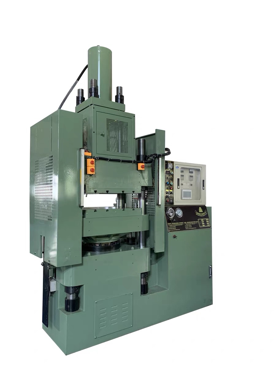
Large Thermoset Hydraulic Transfer Molding Press
Han Chang Machinery manufactures this large Bakelite transfer molding machine for transfer-grade phenolic (PF/Bakelite) and urea-formaldehyde (UF) compounds, used in terminal blocks, insulating bodies and metal-insert parts. Operators manually charge the upper pot. After mold closure, an upper hydraulic plunger transfers compound through runners and gates into the cavities for heat curing.
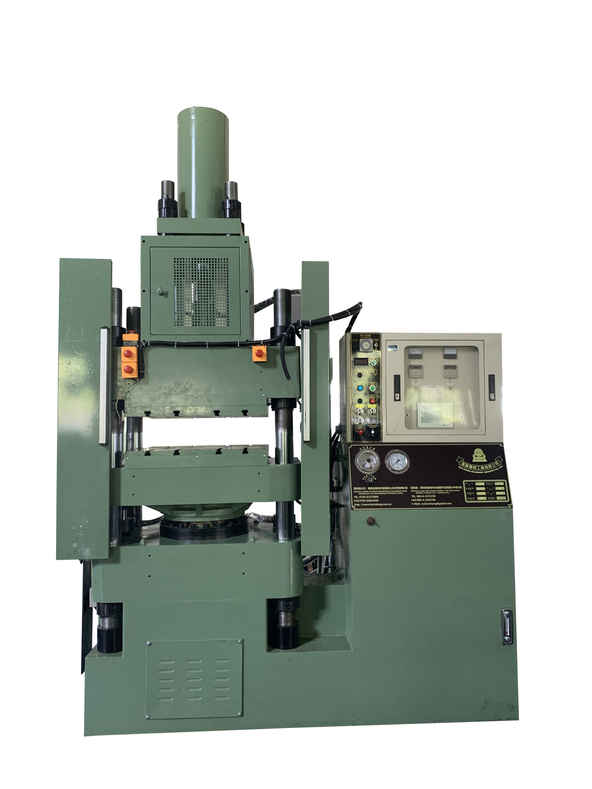
Machine advantages
A large tool does not necessarily make a large part. Multiple cavities, terminal-location features and the path needed to remove a molding all contribute to the space the press must accommodate. This large press addresses those tooling and handling needs using pot-type thermoset transfer: compound loading takes place at the pot, inserts are located in the mold, and filling follows closure. Insert-free insulation supports use the same process.
Choose around the complete tool
A multicavity tool includes more than the molded parts: cavity spacing, runners, mounting points and insert-location features all need room. The reason to consider a large transfer press is to accommodate that complete molding task. It lets buyers compare equipment against the intended tooling layout rather than rule out a large machine because each individual part is small.
Keep compound loading at the pot
The plunger sends the charge through the runner system after the mold closes. Operators do not need to place compound directly into every cavity across a large tool. This separates compound charging from the work of positioning closely spaced terminals or other inserts, while runners and gates establish the feed paths to the molding areas.
Mold several connection points into one body
Terminals, bushings and nuts are located before filling, allowing the insulating body to cure around the specified metal areas. For a base with multiple electrical connections or fastening points, transfer insert molding combines the metal and thermoset structure during body molding. Tooling shutoffs keep required threads, openings and contact surfaces exposed.
Select mold space that also works for handling
A mold carrying protruding terminals needs room for more than installation. Insert placement, loading tools and the finished part’s removal path all contribute to working clearance. Large-press selection brings these movements into the platen, opening and stroke comparison, so the purchase addresses usable production space rather than clamping tonnage alone.
Pot-type transfer molding process
Load the complete molding charge
Prepare compound for all cavities, runners and pot-cull residue. The operator manually places the measured charge in the upper transfer pot.
Locate the metal, if required
Position terminals, bushings or nuts in the mold before closure. Omit this task for insert-free parts. Pot charging and insert loading can be ordered to suit the working arrangement.
Close the tool before filling
The mold closes and is held clamped, establishing the cavities and insert positions before compound enters through the feed system.
Drive the plunger downward
The upper hydraulic cylinder pushes the plunger into the charge. Compound travels through the sprue, runners and gates to fill the closed cavities and the intended areas around any inserts.
Cure with mold heat and pressure
The thermoset compound cures in the heated mold during the pressure-holding stage. The compound grade, flow path, wall sections and tool design guide the molding conditions.
Remove moldings and residue
After curing, the mold opens. The operator removes the parts along the demolding path and clears runner and pot-cull residue before preparing the next cycle.
Materials and product applications
Multi-terminal blocks and terminal-strip bases
An insulating base holds a row of metal terminals and separates adjacent wiring connections in electrical or control equipment. Transfer molding feeds the barriers, mounting areas and insert pockets after the terminals have been located and the mold has closed. Terminal orientation and multicavity spacing can make the complete tool substantially larger than one finished base. This is a practical reason to consider a large press for small electrical components.
Insulating bodies with bushings and threaded nuts
Copper bushings and metal nuts provide connection or fastening points; the surrounding thermoset body provides support and electrical separation. For a base with several metal locations, molding around prepositioned inserts avoids a separate press-fitting operation for those inserts. Tooling shutoffs preserve exposed bores, threads and contact faces. Protruding inserts also determine the direction and clearance needed to remove the finished body.
Switch bodies and rotary-switch bases
Switch bases carry fixed contacts and operating components, with ribs and barriers separating conductive areas. Pot-type transfer is useful for designs that combine contact inserts with the molded insulating structure: gates deliver compound to the closed cavity around the located metal. A multicavity switch tool brings repeated parts into one runner network, making cavity layout, feed distribution and whole-tool handling relevant to large-press selection.
Socket insulation supports and fuse holders
Socket supports locate contact strips, while fuse holders support fuse clips and separate them from surrounding components. Insert-bearing designs can be molded around prepositioned contacts; insert-free bases can receive their contacts during later assembly. A multicavity transfer tool feeds these repeated components from one pot instead of requiring direct compound loading into each cavity. The mold layout, rather than the product name alone, determines the equipment space required.
Insert-free brackets, spacers and support blocks
Appliance insulation brackets, electrical-component spacers and support blocks hold components or separate conductive and hot areas. Designs with mounting holes, ribs or multiple cavities can use runner-fed transfer molding without metal inserts. Compound loading remains at the pot even when molding areas are distributed across a larger tool. Choose a transfer-grade PF or UF compound and part design for the required electrical, thermal and mechanical duty.
Specifications and machine selection
Select the large press around the complete tool, molding charge and working access. Clamping force, platen dimensions, daylight and stroke, together with transfer-pot capacity and plunger conditions, must be stated in the selected large machine’s specification and formal quotation. The selection points below connect those equipment requirements to the actual mold.
Clamping force for the complete mold
Use projected cavity area, molding pressure and tooling requirements to establish the clamping load. For multicavity work, consider the whole mold rather than one part. Clamping resists mold-opening forces during filling; the pressure driving compound through the feed system is a separate transfer requirement.
Mold footprint and platen fit
Relate the complete mold length and width, mounting points and feed interface to the platen and available mounting area. Include runners, cavity spacing and insert-location features. Finished-part dimensions do not describe the full tool envelope.
Daylight, stroke and handling clearance
Compare mold closed height and required opening with protruding terminals, loading tools and the part-removal direction. Allow space for insert placement and removal of the complete molding, not simply enough daylight to install the closed tool.
Transfer pot and plunger sizing
The charge includes every cavity, the runners and pot-cull residue. Match feed form and total material demand to pot capacity, plunger diameter and stroke. Compound flow, gates and runner resistance then guide the transfer conditions needed to fill that tool.
Flow distribution and heat curing
Bring runner balance, gate positions, mold venting and wall-section changes into the multicavity tool design. Match mold temperature and pressure-holding conditions to the PF or UF grade, with heating requirements included in the equipment specification. More clamping force is not a substitute for a suitable feed layout.
For existing tooling, start with its footprint and closed height, then add cavity layout, complete charge and the removal path. A part photo or drawing is also a useful starting point for a new product. Compare machine specifications against the same mold, compound and operating arrangement to make quotations meaningful.
Standard-machine reference specifications
The following tables are standard-series comparison data, not specifications for the large press. Use the selected large-machine specification for its actual ratings.
Spec / Type HCF-50
| Clamping force (Ton) | 50 |
|---|---|
| Plate size (m/m) | 380×380 |
| Cylinder diameter (m/m) | 190 |
| Stroke (m/m) | 300 |
| Daylight (m/m) | 580 |
| Pump pressure (kg/cm2) | 210 |
| Motor (HP) | 3 |
| Heater capacity (Kw) | 5 |
| Oil reservoir capacity (gallon) | 50 |
| Machine size LxWxH (m/m) | 1600x1050x2350 |
| Net weight approx (kg) | 2000 |
Spec / Type HCF-70
| Clamping force (Ton) | 70 |
|---|---|
| Plate size (m/m) | 420×455 |
| Cylinder diameter (m/m) | 212 |
| Stroke (m/m) | 380 |
| Daylight (m/m) | 620 |
| Pump pressure (kg/cm2) | 210 |
| Motor (HP) | 3 |
| Heater capacity (Kw) | 5.5 |
| Oil reservoir capacity (gallon) | 55 |
| Machine size LxWxH (m/m) | 1600x1150x2400 |
| Net weight approx (kg) | 2650 |
Spec / Type HCF-80
| Clamping force (Ton) | 80 |
|---|---|
| Plate size (m/m) | 485×465 |
| Cylinder diameter (m/m) | 236 |
| Stroke (m/m) | 410 |
| Daylight (m/m) | 630 |
| Pump pressure (kg/cm2) | 210 |
| Motor (HP) | 5 |
| Heater capacity (Kw) | 6 |
| Oil reservoir capacity (gallon) | 70 |
| Machine size LxWxH (m/m) | 1720x1200x2605 |
| Net weight approx (kg) | 3150 |
Spec / Type HCF-100
| Clamping force (Ton) | 100 |
|---|---|
| Plate size (m/m) | 600×550 |
| Cylinder diameter (m/m) | 265 |
| Stroke (m/m) | 460 |
| Daylight (m/m) | 750 |
| Pump pressure (kg/cm2) | 210 |
| Motor (HP) | 5 |
| Heater capacity (Kw) | 10.6 |
| Oil reservoir capacity (gallon) | 100 |
| Machine size LxWxH (m/m) | 1840x1250x2825 |
| Net weight approx (kg) | 4100 |
Spec / Type HCF-150
| Clamping force (Ton) | 150 |
|---|---|
| Plate size (m/m) | 660×620 |
| Cylinder diameter (m/m) | 300/315 |
| Stroke (m/m) | 480 |
| Daylight (m/m) | 780 |
| Pump pressure (kg/cm2) | 210 |
| Motor (HP) | 7.5 |
| Heater capacity (Kw) | 10.6 |
| Oil reservoir capacity (gallon) | 100 |
| Machine size LxWxH (m/m) | 2025x1350x2825 |
| Net weight approx (kg) | 4910 |
Spec / Type HCF-200
| Clamping force (Ton) | 200 |
|---|---|
| Plate size (m/m) | 660×620
720×720 |
| Cylinder diameter (m/m) | 368 |
| Stroke (m/m) | 500 |
| Daylight (m/m) | 820 |
| Pump pressure (kg/cm2) | 210 |
| Motor (HP) | 10 |
| Heater capacity (Kw) | 15.2 |
| Oil reservoir capacity (gallon) | 120 |
| Machine size LxWxH (m/m) | 2300x1350x3170 |
| Net weight approx (kg) | 7500 |
Production planning and selection support
An existing installation may be limited by mold fit, insert-loading access or the charge required by a new tool. Han Chang can help connect those specific needs to large-press selection. Comparing the old and proposed tool layouts separates the required machine changes from mold-interface work.
Loading a row of terminals, removing several parts and clearing the runners and pot are real production tasks. Include them in the equipment discussion alongside transfer and curing. This helps relate the molding plan to operator positions, charge preparation and the area for finished parts.
State the press, tooling-interface work and peripheral supply separately in the quotation. Factory planning also needs mold-transport routes, power, headroom and access for cleaning and maintenance. These details make the large-machine purchase easier to compare and integrate with the existing workshop.
Buyer questions
When is a large transfer press worth considering?
Consider a large press when the complete mold footprint, multicavity arrangement or insert-handling space exceeds the suitable conditions of the existing equipment. Small parts can still require a large tool. If a standard machine already meets the clamping, mold-space, charge and access requirements, compare the standard Thermoset Hydraulic Transfer Molding Machine specifications before deciding where the larger investment is needed.
Is this the same as a large Bakelite injection molding machine?
Not necessarily. This large Bakelite transfer molding press uses a manually charged pot and upper hydraulic plunger. The mold closes first, compound enters through runners and gates, and mold heat and pressure cure it. A screw-type Bakelite injection machine plasticizes and feeds compound through a different arrangement. Specify pot-type thermoset transfer when requesting equipment so quotations cover the intended process.
How should I estimate output from a multicavity mold?
Use the complete cycle: manual charging, insert placement, closing and transfer, curing, demolding and cleanup. More cavities increase the number of parts per cycle but also change the charge and handling work. Runner layout and compound cure time affect the result as well. Relate the target shift output to these tasks when selecting the cavity count, equipment and operator arrangement.
What matters when molding several terminals or nuts into one part?
Each insert needs a defined tooling location before closure and retention against compound-flow forces. Gates and shutoffs determine the covered areas while leaving required threads and contacts exposed. The press opening must also accommodate protruding metal, loading tools and the removal path of the finished part. For multiple-insert tooling, these handling conditions are as relevant to machine selection as clamping force.
Which phenolic and UF compounds should be specified?
Use transfer-grade phenolic (PF/Bakelite) or urea-formaldehyde (UF) molding compounds chosen for the part’s electrical, thermal and mechanical duty. Match the grade’s flow and cure data to the pot, gates and mold temperature. For BMC/DMC short-fiber compounds, match the feed form, fiber content, flow and wear conditions to the pot, plunger and tooling. Share the compound grade and part drawing with Han Chang to discuss suitability and the required transfer configuration.
Does adding cavities only require a larger transfer pot?
It also changes the complete tool footprint, clamping requirement, feed distribution and total charge. Plunger diameter, stroke and transfer conditions must suit the compound flow as well as the pot volume. Include runners and pot-cull residue in material-cost comparisons: cured thermoset residue cannot simply be remelted and fed back like ordinary thermoplastic scrap.
What determines the price of a large thermoset transfer press?
Price follows the selected press, mold accommodation, transfer arrangement and agreed supply scope—not the large-press name alone. Start a quotation with the part photo or drawing, compound and intended use. Add existing mold dimensions, cavities and insert details when available. Han Chang can help match those requirements without asking you to guess tonnage or prepare a complete machine specification first.
Match a large transfer press to your complete tool
Send Han Chang a part photo or mold drawing and tell us about the phenolic or UF components you plan to make. We can help relate the mold layout, complete charge and insert-handling needs to a large-press specification and quotation.
Email your product information · Contact Han Chang on WhatsApp
Machine view