
Carbon Fiber / Glass Fiber Hot Press Molding Machine | Ejector Series
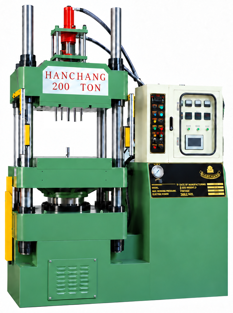
Make part release a priority in your next composite press purchase. Han Chang’s ejector-series carbon fiber / glass fiber hot press molding machine forms and cures suitable reinforced composite molding materials under heat and pressure. An upper or lower ejector can be added on request to push the molded product out of the tool for easier manual removal.
Machine advantages
Choose this series when convenient demolding and hands-on part removal matter to your production. From bicycle components and automotive shells to electronics housings, the press brings molding requirements and the tool’s ejection design into the same equipment decision. With 37–800 ton molding-force specifications, you can match the press to your material and mold while making repeated removal tasks easier and more efficient.
Make the part easier to take from the mold
The ejector pushes the molded product out of the tool so the operator can remove it more conveniently. If part release is a recurring concern on your shop floor, this is a practical feature to specify when buying a composite compression molding press.
Choose ejection around the tool
Specify an upper or lower ejector according to where the part remains after opening and how the mold is designed to release it. Matching this option to your tooling helps turn a general press requirement into a useful production configuration.
Support consistent molding and efficient handling
Appropriate heat, molding pressure and cure time, together with suitable material and tooling, provide the basis for consistent quality. Planning ejection alongside those requirements gives manual part removal the attention it needs, helping the work after curing run more smoothly.
Compare mold space as well as force
The specification range lets you compare molding force, platen size, daylight and stroke against the job. Include the position of the ejected part and the room needed to take it out by hand, so the selected press fits both the mold and the handling task.
Heated compression molding
Place the composite charge
Load the appropriate carbon-fiber- or glass-fiber-reinforced molding material into the mold, following the part’s charge-placement requirements.
Close, compress and cure
Form and cure the material in the closed mold under heat and pressure. Temperature, molding pressure and cure time follow the requirements of the material and component.
Open, eject and remove manually
After curing, open the mold and use the specified upper or lower ejector in accordance with the tool’s ejection design. The ejector pushes the product out of the mold; the operator then removes the part.
Materials and applications
Bicycle components and sporting goods
Applications include bicycle frame components, forks, one-piece handlebars, carbon fiber wheel rims, rackets and skis. Their different shapes and retained positions in the tool call for appropriate release arrangements. Tool-matched ejection makes it easier to plan how the operator takes each molded component out.
Automotive shells and aerodynamic parts
Rear spoilers, mirror housings, front-lip aerodynamic parts and battery-pack housings are among the composite molding applications. For shell production, consider the release direction and the room needed to handle the part as well as molding force. This makes the equipment decision useful beyond the pressing stage.
Drone structures and electronics housings
Drone bodies and wings, laptop housings and protective covers for consumer electronics can use suitable composite molding materials. Cosmetic surfaces and acceptable ejector contact locations are important tooling considerations, allowing convenient removal to be planned around the actual component.
Helmet shells
Composite helmet shells combine curved surfaces with a tool-specific parting and release arrangement. An ejector specified around that tooling can push the shell out for easier manual removal. Finished helmets require performance testing and qualification for their intended use.
Medical panels and assistive-device components
Applications include composite X-ray table panels and prosthetic or orthotic components. Flat panels and shaped supports have different handling needs, so part shape and removal space belong in the press-selection discussion. Finished medical products require the testing and regulatory qualification applicable to their intended use.
Robotic grippers and electrical insulating enclosures
Composite molding can form the required structural shape of robotic gripper components. Electrical insulating enclosures use an appropriate glass-fiber-reinforced molding material suited to the electrical application. Walls, local features and accessible handling points help guide the tool’s ejection arrangement.
Specifications and selection
The Ejector Series uses 12 specifications, from HCB-37 through HCB-800, covering 37–800 ton molding forces. Compare platen dimensions, daylight, stroke and heater capacity in the model tables below, then specify the upper or lower ejector required by your tooling.
Model HCB-37
| Clamping force (Ton) | 37 |
|---|---|
| Plate size (m/m) | 330×340 |
| Cylinder diameter (m/m) | 150 |
| Stroke (m/m) | 370 |
| Daylight (m/m) | 450 |
| Pump pressure (kg/cm2) | 210 |
| Motor (HP) | 3 |
| Heater capacity (Kw) | 4.8 |
| Oil reservoir capacity (gallon) | 56 |
| Machine size LxWxH (m/m) | 1384x 900x 1690 |
| Net weight approx (kg) | 1100 |
Model HCB-50
| Clamping force (Ton) | 50 |
|---|---|
| Plate size (m/m) | 380×380 |
| Cylinder diameter (m/m) | 190 |
| Stroke (m/m) | 370 |
| Daylight (m/m) | 600 |
| Pump pressure (kg/cm2) | 210 |
| Motor (HP) | 3 |
| Heater capacity (Kw) | 5 |
| Oil reservoir capacity (gallon) | 56 |
| Machine size LxWxH (m/m) | 1555x 1050x 2060 |
| Net weight approx (kg) | 1400 |
Model HCB-80
| Clamping force (Ton) | 80 |
|---|---|
| Plate size (m/m) | 485×465 |
| Cylinder diameter (m/m) | 236 |
| Stroke (m/m) | 410 |
| Daylight (m/m) | 630 |
| Pump pressure (kg/cm2) | 210 |
| Motor (HP) | 3 |
| Heater capacity (Kw) | 7.6 |
| Oil reservoir capacity (gallon) | 70 |
| Machine size LxWxH (m/m) | 1720x1200x2115 |
| Net weight approx (kg) | 2750 |
Model HCB-100
| Clamping force (Ton) | 100 |
|---|---|
| Plate size (m/m) | 540×605 |
| Cylinder diameter (m/m) | 265 |
| Stroke (m/m) | 460 |
| Daylight (m/m) | 690 |
| Pump pressure (kg/cm2) | 210 |
| Motor (HP) | 5 |
| Heater capacity (Kw) | 10.6 |
| Oil reservoir capacity (gallon) | 100 |
| Machine size LxWxH (m/m) | 1940x1200x2370 |
| Net weight approx (kg) | 3700 |
Model HCB-150
| Clamping force (Ton) | 150 |
|---|---|
| Plate size (m/m) | 660×620 |
| Cylinder diameter (m/m) | 300/315 |
| Stroke (m/m) | 480 |
| Daylight (m/m) | 700 |
| Pump pressure (kg/cm2) | 210 |
| Motor (HP) | 7.5 |
| Heater capacity (Kw) | 10.6 |
| Oil reservoir capacity (gallon) | 100 |
| Machine size LxWxH (m/m) | 2030x1350x2370 |
| Net weight approx (kg) | 4000 |
Model HCB-200
| Clamping force (Ton) | 200 |
|---|---|
| Plate size (m/m) | 660×620
720×720 |
| Cylinder diameter (m/m) | 368 |
| Stroke (m/m) | 500 |
| Daylight (m/m) | 820 |
| Pump pressure (kg/cm2) | 210 |
| Motor (HP) | 10 |
| Heater capacity (Kw) | 15.2 |
| Oil reservoir capacity (gallon) | 120 |
| Machine size LxWxH (m/m) | 2300x1350x2670 |
| Net weight approx (kg) | 4500
5700 |
Model HCB-250
| Clamping force (Ton) | 250 |
|---|---|
| Plate size (m/m) | 720×720 |
| Cylinder diameter (m/m) | 400 |
| Stroke (m/m) | 520 |
| Daylight (m/m) | 810 |
| Pump pressure (kg/cm2) | 210 |
| Motor (HP) | 10 |
| Heater capacity (Kw) | 18.8 |
| Oil reservoir capacity (gallon) | 150 |
| Machine size LxWxH (m/m) | 2410x1350x2780 |
| Net weight approx (kg) | 5800
6200 |
Model HCB-300
| Clamping force (Ton) | 300 |
|---|---|
| Plate size (m/m) | 720×720
900×860 |
| Cylinder diameter (m/m) | 450 |
| Stroke (m/m) | 560 |
| Daylight (m/m) | 810 |
| Pump pressure (kg/cm2) | 210 |
| Motor (HP) | 15 |
| Heater capacity (Kw) | 20 |
| Oil reservoir capacity (gallon) | 200 |
| Machine size LxWxH (m/m) | 2480x1490x2945 |
| Net weight approx (kg) | 6500
8200 |
Model HCB-400
| Clamping force (Ton) | 400 |
|---|---|
| Plate size (m/m) | 660×620 720×720 980×860 |
| Cylinder diameter (m/m) | 500 |
| Stroke (m/m) | 560 |
| Daylight (m/m) | 950 |
| Pump pressure (kg/cm2) | 210 |
| Motor (HP) | 15 |
| Heater capacity (Kw) | 27 |
| Oil reservoir capacity (gallon) | 250 |
| Machine size LxWxH (m/m) | 2580x1500x3800 |
| Net weight approx (kg) | 6500
7200 8200 |
Model HCB-500
| Clamping force (Ton) | 500 |
|---|---|
| Plate size (m/m) | 800×800
900×900 1140×1100 |
| Cylinder diameter (m/m) | 560 |
| Stroke (m/m) | 580 |
| Daylight (m/m) | 1000 |
| Pump pressure (kg/cm2) | 210 |
| Motor (HP) | 15 |
| Heater capacity (Kw) | 30 |
| Oil reservoir capacity (gallon) | 250 |
| Machine size LxWxH (m/m) | 2810x1705x3135 |
| Net weight approx (kg) | 12000
13500 15800 |
Model HCB-600
| Clamping force (Ton) | 600 |
|---|---|
| Plate size (m/m) | 900×900
1200×1140 |
| Cylinder diameter (m/m) | 620 |
| Stroke (m/m) | 610 |
| Daylight (m/m) | 1020 |
| Pump pressure (kg/cm2) | 210 |
| Motor (HP) | 20 |
| Heater capacity (Kw) | 30 |
| Oil reservoir capacity (gallon) | 300 |
| Machine size LxWxH (m/m) | 3000x1750x4100 |
| Net weight approx (kg) | 14200
16000 |
Model HCB-800
| Clamping force (Ton) | 800 |
|---|---|
| Plate size (m/m) | 1800×1400 |
| Cylinder diameter (m/m) | 700 |
| Stroke (m/m) | 700 |
| Daylight (m/m) | 1060 |
| Pump pressure (kg/cm2) | 210 |
| Motor (HP) | 30 |
| Heater capacity (Kw) | 40 |
| Oil reservoir capacity (gallon) | 355 |
| Machine size LxWxH (m/m) | 3220x1850x4350 |
| Net weight approx (kg) | 26000 |
Match molding force to the process pressure, projected molding area and cavity count. Check the mold footprint, closed height and opening needs against the press data, including space for manual removal after ejection. A part drawing and any existing tooling details are a useful starting point.
Mold and press selection
Start with the part you need to release
Send Han Chang a product photo or drawing and explain how the part is currently removed. Tell us where it remains when the mold opens and which handling step you want to improve. You can start the discussion before choosing a press tonnage.
Put the required ejector in the quotation
If you have tooling, include its footprint, closed height and ejection details. We can discuss force, mold space and the upper or lower ejector option together. Existing requirements for ejector stroke or force are useful inputs for defining the quoted configuration.
Buyer questions
Why choose an ejector-series composite compression molding press?
Choose it when easier mold release and manual part removal are priorities. Han Chang’s Ejector Series hot press forms and cures suitable carbon fiber or glass fiber composite molding materials. An upper or lower ejector can be specified on request to push the product out of the mold, making the operator’s removal task more convenient and efficient.
How do I choose an upper or lower ejector?
Start with where the part remains after the mold opens, the tool’s ejection design and how the operator will take the part away. An upper or lower ejector is an option added to suit those requirements. Product and mold drawings provide a useful basis for selecting the configuration.
Which ejectors are fitted to the machine in the photo?
The photographed machine has both upper and lower ejection. For your order, the upper or lower ejector option is selected around your tooling requirements and identified in the quotation.
How is the part removed after ejection?
The ejector pushes the molded product out of the tool, and the operator then removes it by hand. Consider the part’s position after ejection, its shape and the available handling space when planning the mold and press configuration.
What carbon fiber and glass fiber products can this press mold?
Applications include bicycle components, rackets, skis, automotive shells, drone structures and electronics housings. Each uses the appropriate reinforced composite molding material, tooling and heated curing conditions. The ejector option is matched to the component’s release requirements.
How do molding force and ejector requirements differ?
The 37–800 ton range describes the press’s molding force. Select it using the material’s molding pressure, projected molding area and cavity count. Ejector force and ejector stroke are separate requirements discussed around the tool and part release, alongside the press’s platen size, daylight and stroke.
What should I include when discussing production rate?
Share the material, part drawing, cavity count and target output, together with any known cure time and current removal method. Production planning considers curing, opening, ejection and manual handling. Easier removal helps the handling work, while the material and tooling remain important to the overall cycle.
What determines the price, and how can I request a quote?
The selected molding-force specification, machine dimensions and requested ejector option define the equipment quotation. Send a part photo or drawing, the intended molding material and the removal task you want to improve. Existing mold dimensions and ejection requirements help Han Chang discuss a suitable press configuration; you do not need every parameter settled before contacting us.
Choose a press that makes part removal easier
Show Han Chang your carbon fiber or glass fiber component and tell us how you want to improve demolding. Send a photo or drawing to discuss the Ejector Series, suitable molding force and mold space, and an upper or lower ejector option for your equipment quotation.