
Sliding-Mold Carbon Fiber / Glass Fiber Hot Press Molding Machine
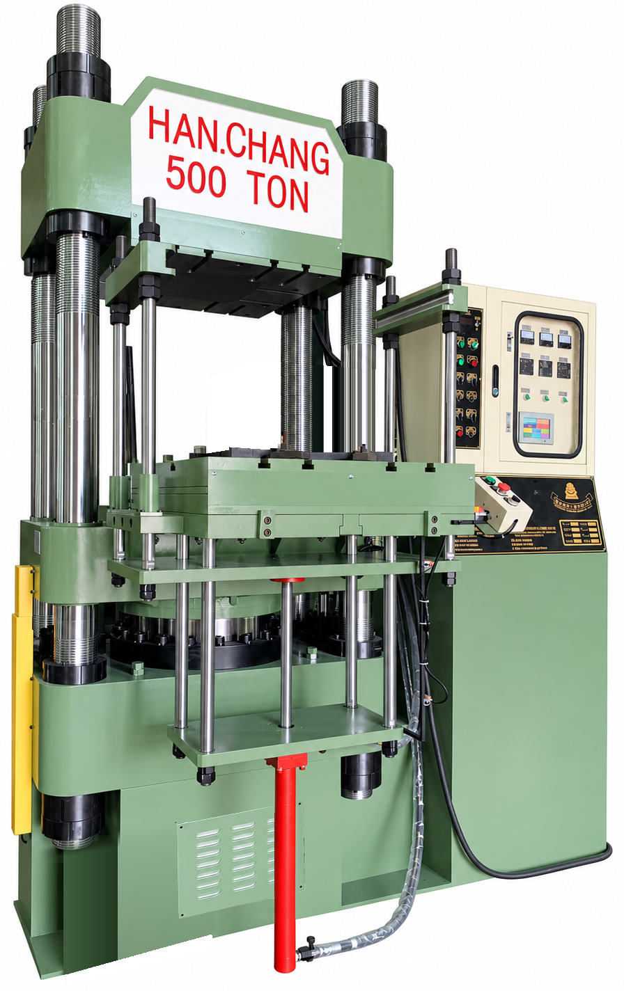
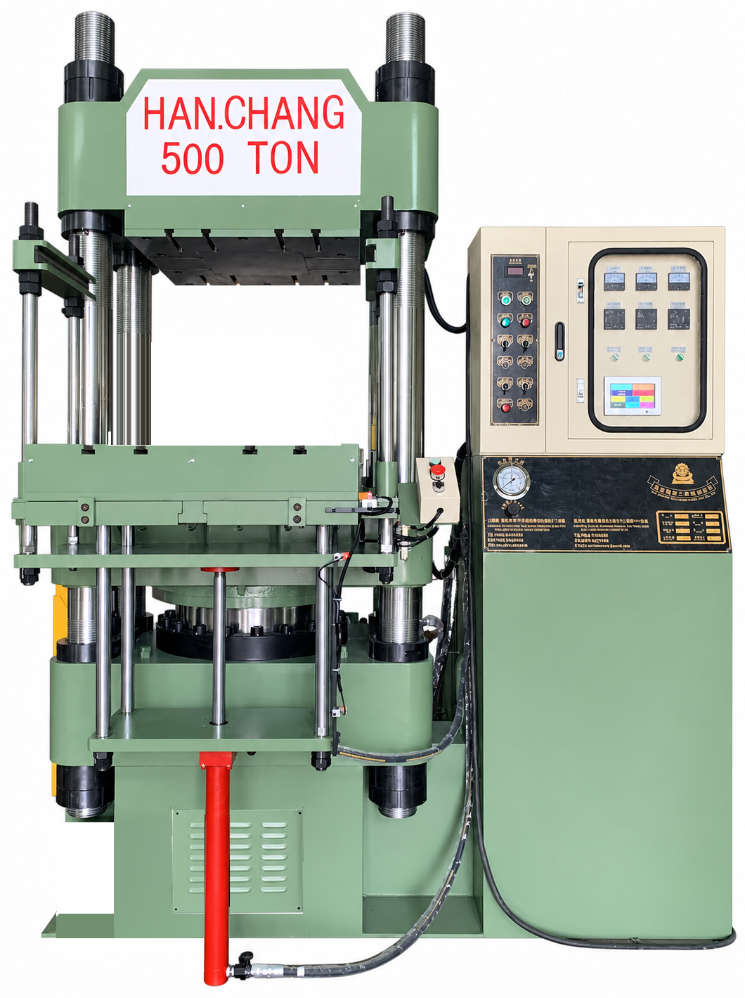
Han Chang’s Sliding-Mold Carbon Fiber / Glass Fiber Hot Press Molding Machine brings the mold out of its molding position for easier manual access outside the press. Operators can remove the part, clean the mold and load the next composite charge in a more convenient position. It is a practical choice for manufacturers who want efficient handling and consistent attention to mold cleanliness alongside heated compression molding.
Machine advantages
The press forms and cures suitable carbon-fiber- and glass-fiber-reinforced composite molding materials for bicycle components, sporting goods, automotive parts and electronics housings. Choose from 37–800 ton clamping-force specifications, with an optional upper or lower ejector to suit the tooling. If mold access is an important part of your equipment decision, put the sliding-mold type on your shortlist.
Give mold cleaning the access it deserves
Moving the mold outside the press makes it easier for operators to reach the surfaces they need to clean and inspect. Removing residual material and checking the mold condition become more convenient, supporting routine mold care and consistent production quality.
Make repeated handling tasks easier
Unloading a molded part and placing the next charge are regular parts of the production cycle. The sliding-mold arrangement provides a more accessible position for this hands-on work, helping improve operating efficiency without making mold preparation an afterthought.
Match part release with practical removal
Specify an upper or lower ejector where the mold’s ejection design calls for it. Ejection assists release from the tool, while the sliding-mold arrangement improves access for manual handling. Considering both together helps the equipment fit the way your parts are removed.
Keep composite molding and tool access in one decision
The machine supports both carbon fiber and glass fiber product applications using suitable reinforced composite molding materials. Select the required force and mold space while also considering how operators will clean, unload and reload the tool between heated molding cycles.
Heated compression molding
See the sliding-mold press
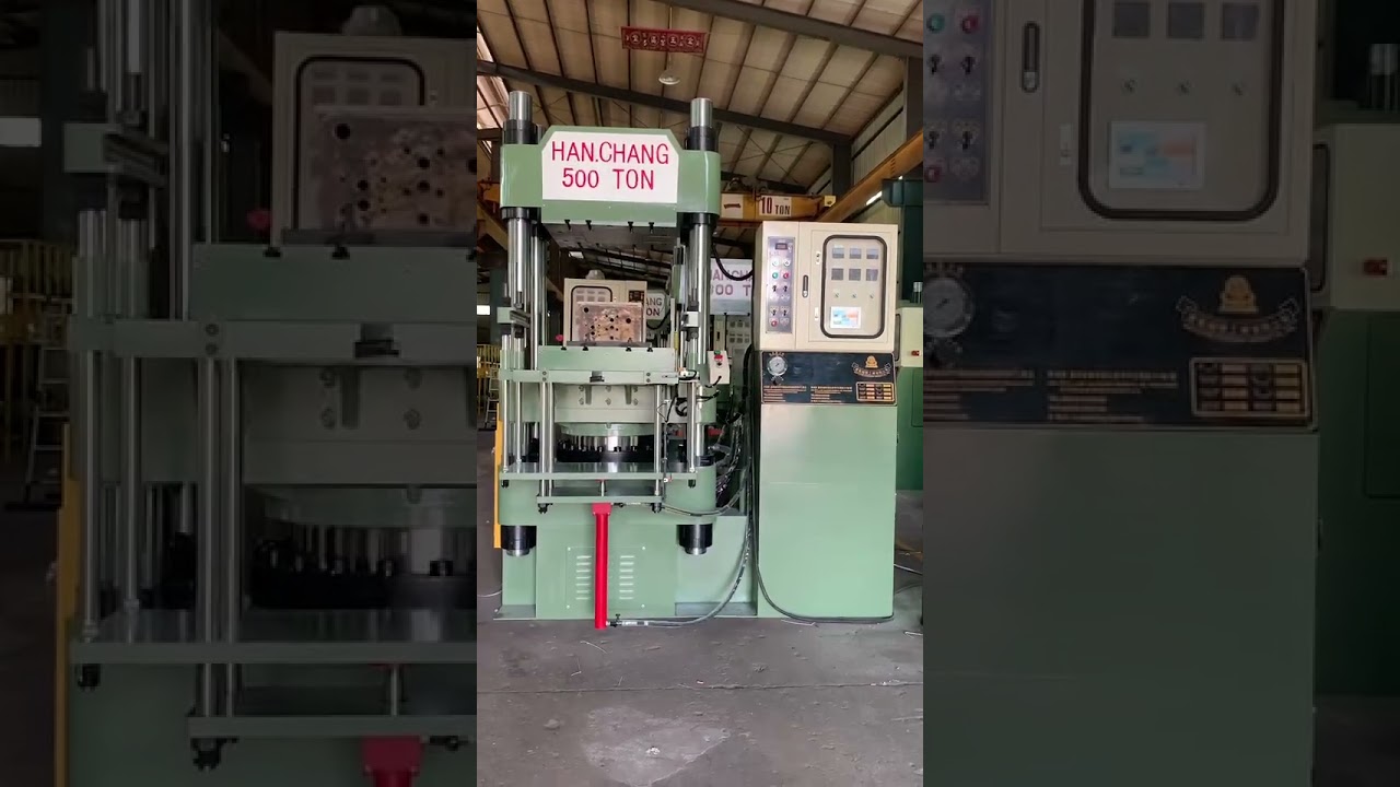
Bring mold handling outside the press. Han Chang’s official short video introduces the sliding-mold carbon fiber and glass fiber hot press configuration, with easier access for manual part removal, mold cleaning and loading the next charge.
Open after curing and move the mold out
Once the current part has cured, open the mold and move it out to the external working position for manual handling.
Remove the part and clean the tool
The operator removes the molded component, clears residual material and checks the mold surface outside the press. Where specified, an upper or lower ejector assists release according to the tool’s ejection design.
Place the next composite charge
Manually load a suitable carbon-fiber- or glass-fiber-reinforced molding material into the prepared mold, following the part’s charge-placement requirements.
Return, close and cure under heat and pressure
Return the mold to its molding position, close it and apply heat and pressure to form and cure the next part. Temperature, molding pressure and cure time follow the requirements of the material and component.
Materials and applications
Bicycle parts and sporting goods
Applications include bicycle frame components, forks, one-piece handlebars, carbon fiber wheel rims, rackets and skis. Bringing the mold outside the press makes routine cleaning and charge placement more accessible, a useful benefit where hands-on mold preparation is an important part of production.
Automotive shells and aerodynamic parts
Produce composite parts such as rear spoilers, mirror housings, front-lip aerodynamic parts and battery-pack housings. The sliding-mold arrangement helps operators handle the molded shell and prepare the tool for the next charge from outside the press.
Drone structures and consumer electronics
Drone bodies and wings, laptop housings and protective covers for consumer electronics are within the application range. Heated compression shapes and cures the suitable composite material; external mold access makes manual surface cleaning and reloading easier to carry out.
Helmet shells
For composite helmet shells, accessible tooling is useful for manual part removal and cleaning between cycles. An optional ejector can assist release where required by the mold design. Finished helmets require performance testing and qualification for their intended use.
Medical panels and assistive-device parts
Applications include composite X-ray table panels and prosthetic or orthotic components. The external mold position helps operators attend to routine tool cleaning and inspection. Finished medical products require the testing and regulatory qualification applicable to their intended use.
Robotic grippers and insulating enclosures
Robotic gripper components can use composite molding to achieve the required structural shape. Electrical insulating enclosures use an appropriate glass-fiber-reinforced molding material suited to the electrical application. The mold can move out for convenient manual removal, cleaning and loading.
Specifications and selection
The sliding-mold press offers 12 specifications, from HCB-37 through HCB-800, covering 37–800 ton clamping forces. Compare platen dimensions, daylight, stroke and heater capacity in the model data to select a press for your tooling and molding requirements.
Model HCB-37
| Clamping force (Ton) | 37 |
|---|---|
| Plate size (m/m) | 330×340 |
| Cylinder diameter (m/m) | 150 |
| Stroke (m/m) | 370 |
| Daylight (m/m) | 450 |
| Pump pressure (kg/cm2) | 210 |
| Motor (HP) | 3 |
| Heater capacity (Kw) | 4.8 |
| Oil reservoir capacity (gallon) | 56 |
| Machine size LxWxH (m/m) | 1384x 900x 1690 |
| Net weight approx (kg) | 1100 |
Model HCB-50
| Clamping force (Ton) | 50 |
|---|---|
| Plate size (m/m) | 380×380 |
| Cylinder diameter (m/m) | 190 |
| Stroke (m/m) | 370 |
| Daylight (m/m) | 600 |
| Pump pressure (kg/cm2) | 210 |
| Motor (HP) | 3 |
| Heater capacity (Kw) | 5 |
| Oil reservoir capacity (gallon) | 56 |
| Machine size LxWxH (m/m) | 1555x 1050x 2060 |
| Net weight approx (kg) | 1400 |
Model HCB-80
| Clamping force (Ton) | 80 |
|---|---|
| Plate size (m/m) | 485×465 |
| Cylinder diameter (m/m) | 236 |
| Stroke (m/m) | 410 |
| Daylight (m/m) | 630 |
| Pump pressure (kg/cm2) | 210 |
| Motor (HP) | 3 |
| Heater capacity (Kw) | 7.6 |
| Oil reservoir capacity (gallon) | 70 |
| Machine size LxWxH (m/m) | 1720x1200x2115 |
| Net weight approx (kg) | 2750 |
Model HCB-100
| Clamping force (Ton) | 100 |
|---|---|
| Plate size (m/m) | 540×605 |
| Cylinder diameter (m/m) | 265 |
| Stroke (m/m) | 460 |
| Daylight (m/m) | 690 |
| Pump pressure (kg/cm2) | 210 |
| Motor (HP) | 5 |
| Heater capacity (Kw) | 10.6 |
| Oil reservoir capacity (gallon) | 100 |
| Machine size LxWxH (m/m) | 1940x1200x2370 |
| Net weight approx (kg) | 3700 |
Model HCB-150
| Clamping force (Ton) | 150 |
|---|---|
| Plate size (m/m) | 660×620 |
| Cylinder diameter (m/m) | 300/315 |
| Stroke (m/m) | 480 |
| Daylight (m/m) | 700 |
| Pump pressure (kg/cm2) | 210 |
| Motor (HP) | 7.5 |
| Heater capacity (Kw) | 10.6 |
| Oil reservoir capacity (gallon) | 100 |
| Machine size LxWxH (m/m) | 2030x1350x2370 |
| Net weight approx (kg) | 4000 |
Model HCB-200
| Clamping force (Ton) | 200 |
|---|---|
| Plate size (m/m) | 660×620
720×720 |
| Cylinder diameter (m/m) | 368 |
| Stroke (m/m) | 500 |
| Daylight (m/m) | 820 |
| Pump pressure (kg/cm2) | 210 |
| Motor (HP) | 10 |
| Heater capacity (Kw) | 15.2 |
| Oil reservoir capacity (gallon) | 120 |
| Machine size LxWxH (m/m) | 2300x1350x2670 |
| Net weight approx (kg) | 4500
5700 |
Model HCB-250
| Clamping force (Ton) | 250 |
|---|---|
| Plate size (m/m) | 720×720 |
| Cylinder diameter (m/m) | 400 |
| Stroke (m/m) | 520 |
| Daylight (m/m) | 810 |
| Pump pressure (kg/cm2) | 210 |
| Motor (HP) | 10 |
| Heater capacity (Kw) | 18.8 |
| Oil reservoir capacity (gallon) | 150 |
| Machine size LxWxH (m/m) | 2410x1350x2780 |
| Net weight approx (kg) | 5800
6200 |
Model HCB-300
| Clamping force (Ton) | 300 |
|---|---|
| Plate size (m/m) | 720×720
900×860 |
| Cylinder diameter (m/m) | 450 |
| Stroke (m/m) | 560 |
| Daylight (m/m) | 810 |
| Pump pressure (kg/cm2) | 210 |
| Motor (HP) | 15 |
| Heater capacity (Kw) | 20 |
| Oil reservoir capacity (gallon) | 200 |
| Machine size LxWxH (m/m) | 2480x1490x2945 |
| Net weight approx (kg) | 6500
8200 |
Model HCB-400
| Clamping force (Ton) | 400 |
|---|---|
| Plate size (m/m) | 660×620 720×720 980×860 |
| Cylinder diameter (m/m) | 500 |
| Stroke (m/m) | 560 |
| Daylight (m/m) | 950 |
| Pump pressure (kg/cm2) | 210 |
| Motor (HP) | 15 |
| Heater capacity (Kw) | 27 |
| Oil reservoir capacity (gallon) | 250 |
| Machine size LxWxH (m/m) | 2580x1500x3800 |
| Net weight approx (kg) | 6500
7200 8200 |
Model HCB-500
| Clamping force (Ton) | 500 |
|---|---|
| Plate size (m/m) | 800×800
900×900 1140×1100 |
| Cylinder diameter (m/m) | 560 |
| Stroke (m/m) | 580 |
| Daylight (m/m) | 1000 |
| Pump pressure (kg/cm2) | 210 |
| Motor (HP) | 15 |
| Heater capacity (Kw) | 30 |
| Oil reservoir capacity (gallon) | 250 |
| Machine size LxWxH (m/m) | 2810x1705x3135 |
| Net weight approx (kg) | 12000
13500 15800 |
Model HCB-600
| Clamping force (Ton) | 600 |
|---|---|
| Plate size (m/m) | 900×900
1200×1140 |
| Cylinder diameter (m/m) | 620 |
| Stroke (m/m) | 610 |
| Daylight (m/m) | 1020 |
| Pump pressure (kg/cm2) | 210 |
| Motor (HP) | 20 |
| Heater capacity (Kw) | 30 |
| Oil reservoir capacity (gallon) | 300 |
| Machine size LxWxH (m/m) | 3000x1750x4100 |
| Net weight approx (kg) | 14200
16000 |
Model HCB-800
| Clamping force (Ton) | 800 |
|---|---|
| Plate size (m/m) | 1800×1400 |
| Cylinder diameter (m/m) | 700 |
| Stroke (m/m) | 700 |
| Daylight (m/m) | 1060 |
| Pump pressure (kg/cm2) | 210 |
| Motor (HP) | 30 |
| Heater capacity (Kw) | 40 |
| Oil reservoir capacity (gallon) | 355 |
| Machine size LxWxH (m/m) | 3220x1850x4350 |
| Net weight approx (kg) | 26000 |
Match force to molding pressure, projected molding area and cavity count, then review the mold’s fit and opening requirements. Include the external position used for cleaning, unloading and reloading in your equipment layout discussion. A part or mold drawing is a useful place to start.
Mold and press selection
Show us the handling task you want to improve
Start with a part photo or drawing and tell Han Chang how the mold is currently cleaned, unloaded and charged. That gives the equipment discussion a practical starting point, even before you have selected a press size.
Include the mold and its working space
If tooling is available, add its footprint, closed height, mounting and ejection details. We can discuss platen size, daylight, stroke and the optional ejector together with the space needed for external mold handling, so the quotation reflects your production setup.
Buyer questions
Why choose a sliding-mold composite compression molding press?
Choose it when convenient access for manual mold cleaning, part removal and loading is a priority. Han Chang’s sliding-mold hot press moves the mold outside the press for these tasks, helping operators maintain mold cleanliness and improve handling efficiency between molding cycles.
What work is done outside the press?
After curing and mold opening, the mold moves out. Operators manually remove the part, clean and inspect the mold surface, and place the next composite charge. The mold then returns to the molding position for closing, heating and compression to cure the next part.
Can this press mold both carbon fiber and glass fiber parts?
Yes. It supports suitable carbon-fiber- and glass-fiber-reinforced composite molding materials, with applications including bicycle parts, automotive shells, sporting goods and electronics housings. Each product uses the appropriate molding material, tool and heated curing conditions.
Is an ejector included with the sliding-mold arrangement?
An upper or lower ejector is an option specified on request. Select it around where the part remains after opening and the tool’s ejection design. The ejector assists mold release; the sliding-mold feature provides access for manual handling outside the press.
How should I compare force, daylight and working space?
Select from 37–800 ton specifications using the material’s molding pressure, projected molding area and cavity count. Compare the mold footprint with the platen size, and its closed height and opening needs with daylight and stroke. Also allow for the operator’s cleaning, removal and loading position when the mold is outside the press.
How does the sliding mold fit into cycle-time planning?
Plan the cycle around curing, opening, mold movement and the manual removal, cleaning and loading steps. Easier access helps the handling work run more smoothly. The material’s cure requirements, tool design and cavity count remain important inputs when discussing your production target.
What do you need for a quotation?
Send a product drawing or photo, the intended composite molding material and a short description of the handling work you want to improve. Existing mold dimensions and ejection details are useful if available. Han Chang can then discuss the press specification and ejector option for your equipment quotation.
Make mold access part of your next press purchase
Tell Han Chang which carbon fiber or glass fiber part you want to make and how you would like to improve cleaning, removal or loading. Send a photo or drawing to discuss a sliding-mold press, suitable force and mold space, and the ejector option for your quotation.